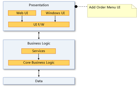
How to Draw Dependency Diagram in Visio
As a workaround you can draw a dependency diagram in Visio manually then link shapes to data with Excel. Tab to the page you want to display and then close Visio.
Create Dependency Diagrams From Your Code Visual Studio Windows Microsoft Docs
Create a Visio Diagram.
. Drag a Summarization structure shape from the PERT Chart Shapes stencil onto the drawing page. Or relationships such as those contained in a knowledge graph. Indicate a dependency relationship between UML elements.
Drag a Dependency shape from UML Static Structure UML Deployment or UML Component onto the drawing page and place it near the elements you want to relate. As a workaround you can draw a dependency diagram in Visio 2013 manually then link shapes to data with Excel. To create the diagram I.
For more information about Link shapes to data in Visio 2013 please refer to. If you do any changes with the linked Excel data the shape information would be updated too in Visio. You can then use dependency diagrams to help you update the code and keep it consistent with your design.
Under Template Categories click Software and then click UML Model Diagram and then click Create. Sign-up now to try out the early preview of the feature. Im looking for a tool that will generate an assemblyproject dependency diagram in Visio or as close as possible to assist me with breaking up some of our system into more manageable trunks.
If you do any changes with the linked Excel data the shape information would be updated too in Visio. In a component diagram components are generic types rather than instances. Examine the linked artifacts.
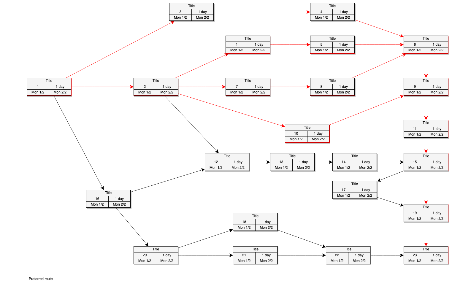
As for all directed graphs dependency graphs also comprise nodes or vertices represented as boxes. By default the drawing opens to the first page. An actor can be a person an organization or another system.
They dont show the order in which steps are performed. In Word click where you want the Visio drawing to appear and then click Paste or press CtrlV. Dependencies indicate that a client component is dependent upon a supplier component in some way.
Click on one of the four direction arrows on a node and select a shape to add it to the canvas as a dependency from that node. Create dependency diagrams from your code. Go to diagramnew choose your storage location and create a new blank diagram if prompted.
With Visios Data Visualizer feature now you can automatically create a Basic Flowchart or Cross-Functional Flowchart from your process map in Excel in no time. Use Solution Explorer to explore namespaces and classes which often correspond well to existing layers. Layer Explorer opens and shows the artifacts that are linked to the selected layers.
After installing VisioPS you an launch an instance of PowerShell and do this. Soon you will be able to create more diagrams too. Double-click the drawing to open it in your Visio application.
Double click on the drawing canvas and select the ellipse shape to add it to the canvas. Drag a second Summarization structure shape onto the drawing page and place it beneath the first shape. Assign these code artifacts to layers by dragging them from Solution Explorer to dependency diagrams.
Use case diagrams show the expected behavior of the system. To show component instances use a deployment diagram. A dependency graph is a graph with directed edges that represent the relationship existing between vertices.
Creately diagrams can be exported and added to Word PPT powerpoint Excel Visio or any other document. The Direct Graph is a simple XML document like this. Its typical usage consists of describing processes such as those in the development of software.
Feb 29 But if you want to generate a dependency diagram automatically it is not possible to achieve it in Visio automatically. You can edit this template and create your own diagram. On the dependency diagram open the shortcut menu for one or more layers and then choose View Links.
This tutorial demonstrates how you can use Microsoft Visio to build a dependency diagram as you work through the process of modelling a database. Use Createlys easy online diagram editor to edit this diagram collaborate with others and export results to multiple image formats. Select a category from the left section of the Data Visualizer box and click your preferred diagram from the right.
Import-Module VisioPS New-VisioApplication New-VisioDocument dg Import-VisioDirectedGraph cfooxml Invoke-VisioDraw dg. Notice how Microsoft Visio Data Visualizer automatically created a diagram created a table in the Excel sheet and populated its cells with some dummy values. On the File menu point to New point to Schedule and then click PERT Chart.
Make sure nothing is selected and then on the Home tab click Copy or press CtrlC. The ability to includeexclude non-project dependencies is a must ie. Glue the endpoint with an arrowhead to a connection point on the element the other element depends on.
You can create a UML use case diagram in Visio to summarize how users or actors interact with a system such as a software application. Dependency is a directed relationship which is used to show that some UML element or a set of elements requires needs or depends on other model elements for specification or implementationBecause of this dependency is called a supplier - client relationship where supplier provides something to the client and thus the client is in some. Create a hierarchical task summary.
Blog Draw Dependency Graphs In Diagrams Net

Micrsoft Visio 2013 How To Build A Dependency Diagram Youtube

Azure Service App Dependency Detection Visio Diagram Support Ctrl Click Google Cloud Billing Export To Bigquery Cloudockit


Comments
Post a Comment